My friend had a Roland Juno G keyboard that after some time get the LCD display broken.
That issue is a common problem. Roland produced some display revision and the new release should fix the issue, but the replacement was very expansive and now is out of production.
The keyboard still works and can be programmed using the pc software but we want to try to get a replacement for cheap.
The original display is a 240×90 display with backlight. Since the issue is that only half of the display is working is clear that the display is equipped with two controller that drives the two half of the display.
The confirmation from this come from the service manual, the display have two CS lines.
The bad thing is that we don’t know anything about the embedded controller and the protocol used by the display. We know just that between then v1 revision and the v2 revision of the display a bootloader and firmware upgrade is required. From information found on some forum it appears that after the LCD replacement the new display doesn’t works correctly and during the upgrade procedure comething is visible on replaced LCD. So the basic protocol is the same between firmware <2.0 and 2.0.1 but we won’t consider the 2.0.1 firmware release.
The idea is to use a microcontroller to intercept the data from the display, convert the protocol and display the data on a completely different display.
I’ve looked all over Amazon and AliExpress to look for a replacement. It doesn’t exists any LCD with similar characteristics and size so I’ve bought a 5.0″ TFT display with an ILI9488 controller and a SPI interface for about 15/17€.
For this kind of operation an Arduino Mega should be the best choice for the number of gpio.
Then I bought an ESP32 Dev board that is much more cheap and should have enough power, gpio for this project. A plus is the WiFi that should make much easier to update the firmware with ArduinOTA.
Since I don’t have the keyboard here yet, I’ve started playing with the firmware, the esp32 and the display.
The firmware is composed of multiple blocks of data with different file and at the end there is the firmware blob. It appears to be compressed with an lz algo.
Hopefully that compression method was used on other Roland products and someone wrote a program to uncompress that format.. I had just to split the file at the right offset to get an uncompressed binary.
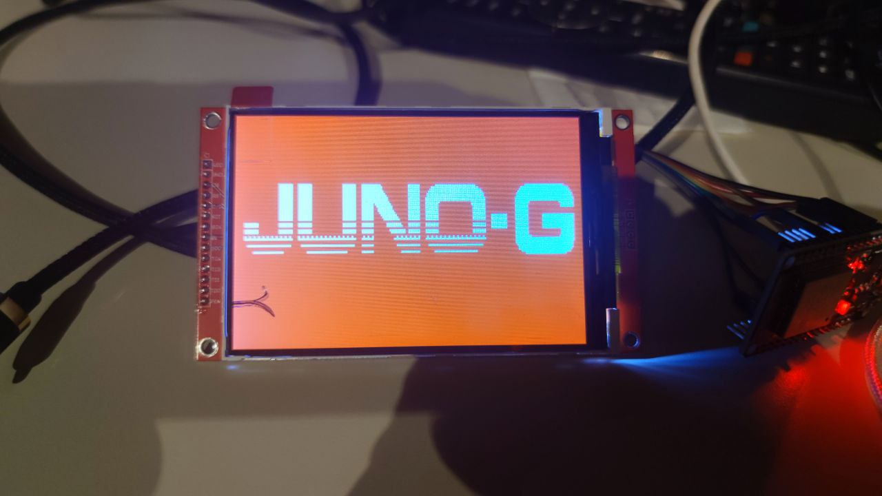
I renamed the file like junog.raw.data and I’ve opened it with gimp. I’ve chooses a 1bit format and moved between the offset and the width and height and after some attempt I was able to locate the offset of the boot splash of the keyboard with the expected size (240 x 96 px).

I’ve converted to a c byte array and included it in a small sketch to be loaded on the esp.
Now is time to put the hand on the keyboard…
Finally i should adapt this sketch to use some interrupt to capture the lcd data from the display.. https://gist.github.com/cnlohr/2b9f8a26e891aa1a118f634cff9d04fe.
https://github.com/EUA/ESP32_LogicAnalyzer
UPDATE:
I was able to get some display output from the keyboard to the new display using the ESP but was an EPIC FAIL!
I had to use i2s and DMA using the CS1 line as a clock for the i2s cirtuit. But the display have 2 CS line and the second i2s circuit can’t be used as another parallel input.
So i moved to Raspberry PI Pico. I had some difficult understanding the state machine, PIO and DMA.
Since the TFT i’ve used have a different resolution, i’ve implemented a simple zoom routine.
This is the source code i wrote.
https://github.com/dpeddi/LCDJunoG
The pinout of the original connector

I’ve finally added a reading of the brightness trimmer and used to change the background color:
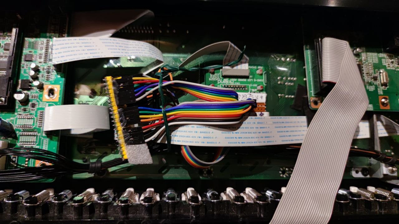
The raspberry pi pico mounted inside the keyboard:
The final result… the display mounted uwing a 3d printed support.
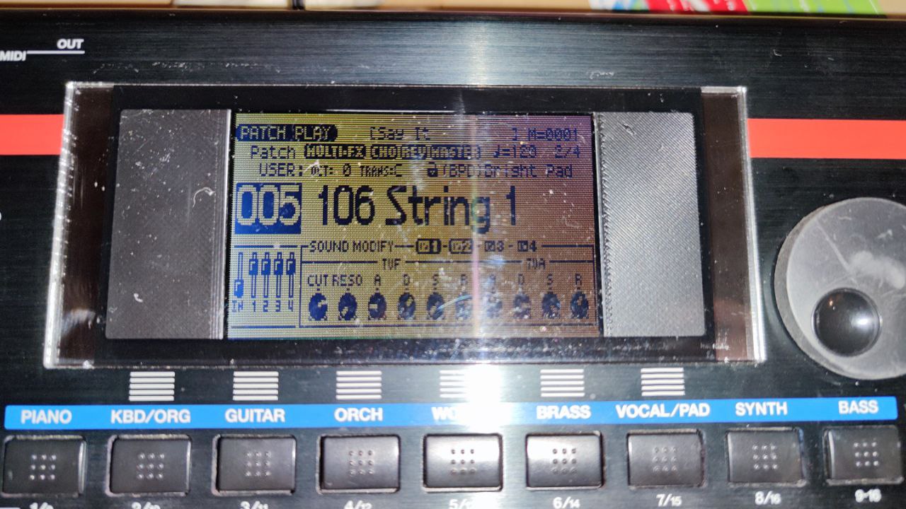
The support isn’t perfect. i did some mistake and it needed some rework with a cutter.